Eight Model Controller
At Meccano exhibitions I typically have many small models running at the same time. Each one incorporates its own small motor which must be run at a suitable speed, which necessitates the use of many small power supply units of differing voltages, each one plugged into its own mains power socket.
To simplify things I created a system that can independently control the speed of each model, with one power supply unit supplying power to the system and all of the models at once.
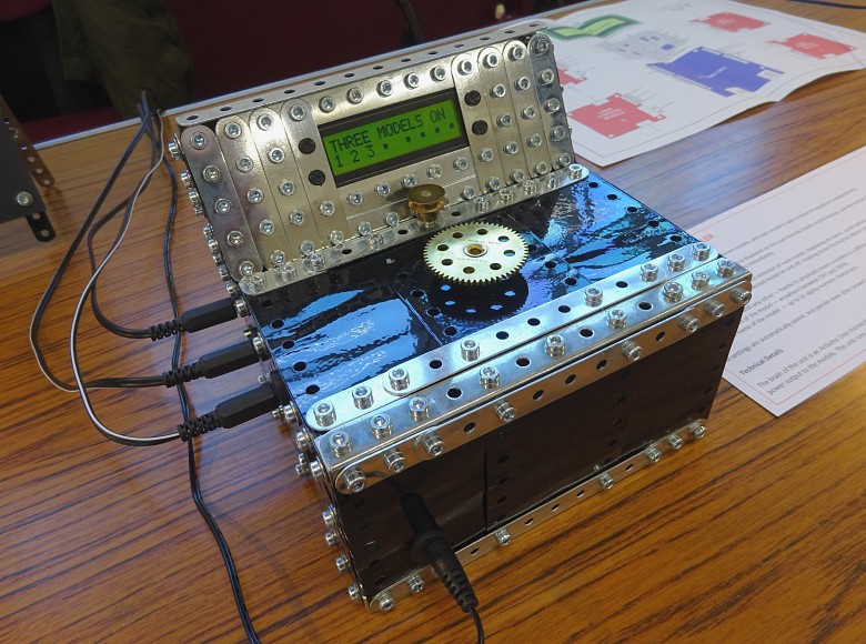
The electronics are housed in a Meccano box with a user-friendly liquid crystal display (LCD) screen and controls.

The eight model controller in operation
Operation
The system is able to independently control the speed of up to eight different models, with each model connected to a separate output jack. All of my models have been modified to use the same style of power jack so that they can be connected to any output jack as required.
The LCD screen shows the status of the system and allows you to change settings using a button and a rotary switch.
In normal operation the LCD screen will show you which models are ON, but when you first power up the system all of the models will be in the OFF state.

Normal operation with the models connected to output jacks 2 and 7 ON
Pressing the button during normal operation will activate/deactivate the EMERGENCY STOP mode. In this mode all of the models are immediately returned to the OFF state.

EMERGENCY STOP mode active
Turning the rotary switch during normal operation allows for the selection of each model, displaying its name, speed setting, and which of the eight output jacks it is connected to on the LCD screen. Pressing the button will then toggle the selected model ON and OFF.

A model of a beam engine connected to output jack 2 running at 35% speed
Holding down the button allows you to swap the model with any other — handy to physically move a model to a different output jack. Turn the rotary switch to select the new output jack.

The model connected to output jack 2 being swapped with the model connected to output jack 3
Holding down the button a second time allows you to set the speed of the model — anywhere between OFF and 100%. Turn the rotary switch to select the new speed.

The speed of the model connected to output jack 2 being set to 70%
Holding down the button a third time allows you to set the name of the model — up to 16 alpha-numeric characters taken from A–Z, SPACE and 0–9. Turn the rotary switch to select a character and press the button to advance the cursor to the next character.

The name of the model connected to output jack 2 being set
If you do not move the rotary switch or press the button for five seconds when changing settings, the system will save your changes (a flashing icon indicates saving in progress) and return to normal operation. All settings persist even after power is removed.
The system runs from a 12V DC power supply and this is also the maximum output voltage available to each model.
Construction
The brain of the system is an Arduino Uno microcontroller board. This sends pulse width modulated (PWM) signals to four L298N H-Bridge modules which handle power output to the models.
To upload the Arduino sketch to the Arduino Uno use the standard Arduino IDE software, but when doing so make sure that digital I/O pins 0 and 1 are left unconnected as these are used to communicate with your computer.
The LCD screen is a standard 16 columns x 2 rows unit with an LED backlight, based on the Hitachi HD44780 controller.
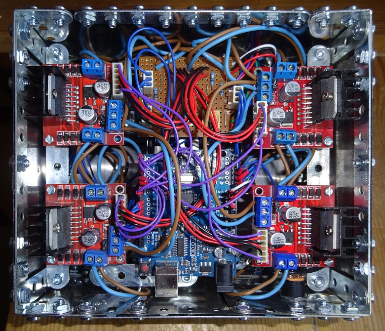
The physical layout and wiring of the system is shown in figure 1. The Arduino Uno microcontroller board, L298N H-Bridge modules and LCD screen are all connected to a central piece of stripboard with additional components including a preset potentiometer which adjusts the contrast and viewing angle of the LCD screen.

Figure 1: The physical layout and wiring of the electronics — Click to enlarge
The electronics are housed in a Meccano box with the eight output jacks to the left and right, the 12V DC power supply input jack to the front, and the LCD, button and rotary switch on the top.

The underside of the Meccano box showing the physical layout and wiring of the electronics
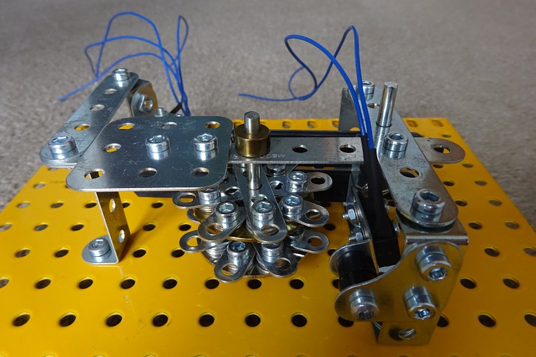
The details of the rotary switch are shown below. It consists of two slightly offset ‘gears’ which engage two microswitches. Thus movement and direction can be determined by the Arduino Uno sketch. It would be quite easy to alter the sketch to eliminate the rotary switch and instead use two normal buttons for up/down adjustment of settings.

A view of the rotary switch showing the offset ‘gears’

A view of the rotary switch showing the microswitches
Parts list
| Part |
Quantity |
| 100Ω 0.25W carbon film resistor |
1 |
| 10kΩ 0.25W carbon film resistor |
3 |
| 10kΩ preset potentiometer |
1 |
| 5.5mm power jack chassis-mounting socket |
9 |
| 5.5mm power jack plug |
9 |
| 3-way 0.1” pitch male PCB connector pin header |
5 |
| 6-way 0.1” pitch male PCB connector pin header |
3 |
| 8-way 0.1” pitch male PCB connector pin header |
1 |
| 3-way 0.1” pitch female PCB connector housing |
3 |
| 6-way 0.1” pitch female PCB connector housing |
6 |
| 0.1” pitch female PCB connector housing crimp pins |
45 |
| SPST microswitch |
3 |
| Arduino Uno microcontroller board |
1 |
| L298N H-Bridge module |
4 |
| 16 columns x 2 rows Hitachi HD44780 controller-based LCD with LED backlight |
1 |
| 21 holes x 16 tracks 0.1” pitch stripboard |
1 |