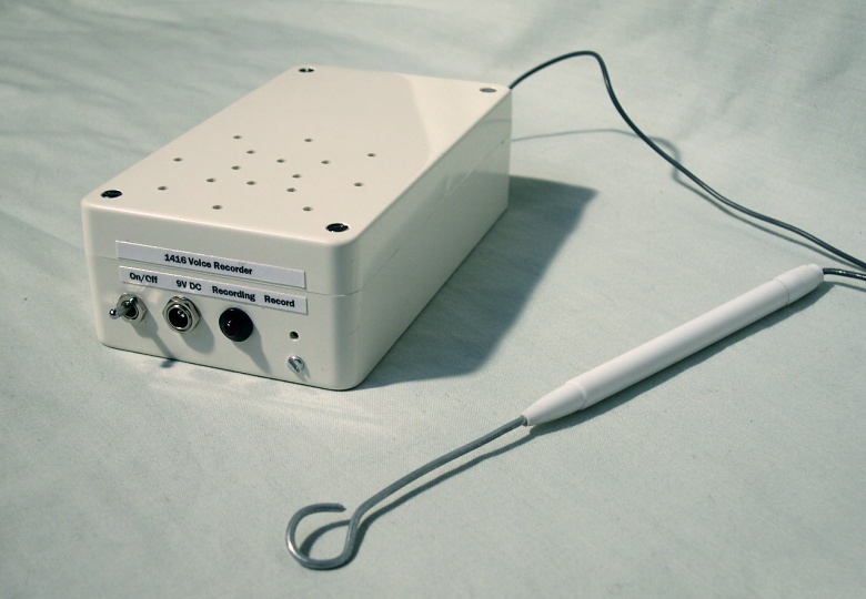
Buzz-wired for Sound
This project adds some value to the classic buzz-wire game of skill, where players must move a loop of wire on a wand along another piece of wire without letting the two touch. If they do touch, a buzzer normally sounds and the player has to start again (or perhaps loses one of a set number of ‘lives’, giving the player a few chances to get a feel for the game).
The difficulty level of the game is decided during construction by choosing the diameter of the wand loop, and by choosing the number of curves and corners in the wire.
When I decided to build a buzz-wire game to raise money at the Foal Farm Animal Rescue Centre country festival, I wanted to have some animal noises instead of a buzz — a barking dog when the wire is touched, and a screeching cat when the player manages to complete the game. I named the game ‘Catch the Cat’, and placed an image of a dog on the wand and an image of a cat at the right-hand side of the wire!
The animal noises are produced by a voice recorder that I designed. It is based on the 1416 Voice Recorder IC manufactured by ISD, which allows two messages of up to 8 seconds each to be recorded and stored, ready for playback at any time, even if power is lost and later restored. You could also store one message of 16 seconds duration instead if you wished.

The voice recorder
Operation
Each message is triggered separately by taking the MESS1 or MESS2 inputs low, as shown in figure 1. The left-hand section of the buzz-wire is connected to MESS1, with the small right-hand section connected to MESS2 so that the second message is triggered when the player lets go of the wand after completing the game. The two sections are separated by a small piece of insulating plastic. The wand loop is connected to the TRIG input, which is internally connected to 0V.

Figure 1: External connections to the voice recorder
To record each message the TRIG input is connected to either MESS1 or MESS2 and the REC SWITCH is held in whilst playing the message into the MIC socket. The REC LED will light during recording but will go out if the recording has used up all the memory.
Circuit description
The circuit is essentially the example given in the 1400 Series Voice Recorder Datasheet shown below:

Figure 2: Example application circuit diagram
The PLAYL button has been removed and its associated 100kΩ resistor retained to pull pin 23 high. The MIC input need not be a microphone as shown, but can be connected to other devices. I have successfully recorded from a CD player and a PC sound card. You could also connect the output to an amplifier to drive a larger speaker if required.
In order to provide two message sections, the additional components in figure 3 have been connected to the PLAYE, A4 and A6 inputs. Taking A4 and A6 high sets the start address to half-way through the memory — 8 seconds. A4 and A6 are normally kept high by the 100kΩ resistor. If MESS2 is brought low by the TRIG input, A4 and A6 go low to select the first address of the memory space. The two NOT gates introduce a propagation delay before PLAYE also goes low and starts playback.
If MESS1 is taken low by the TRIG input, PLAYE is taken low and playback starts from 8 seconds into the memory space since A4 and A6 are still high. The 1N4148 diode stops the NOT gate output from being forced low.

Figure 3: Additional components to allow two messages to be recorded
Construction
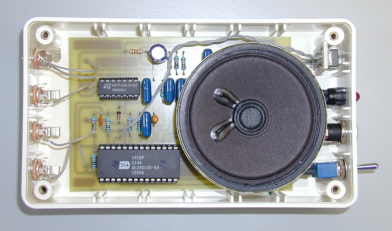
The circuit can be built on a single-sided PCB which will fit in a 14.3cm x 8.2cm box. I have used mono jack plugs for the MIC, TRIG, MESS1, and MESS2 inputs as this suited my application. If you have no need to disconnect the wand, buzz-wire and microphone, you could connect these directly to the PCB. You could also use push buttons between MESS1 and TRIG, and MESS2 and TRIG to use the circuit as a stand-alone voice recorder.

The PCB, speaker, connectors and switches inside the box
In use, you probably don’t want to press REC by accident as it will erase your recordings. Therefore, I made a 3mm hole in the side of the box and placed a small tactile push button behind it so that it could only be pressed by pushing something thin through the hole. This is the purpose of the ‘REC SW PCB’ — it holds the switch in place using the M2.5 nuts and 20mm bolt.
The PWR SWITCH is a normal miniature single-pole toggle switch and the PWR IN is a barrel socket like those on portable CD players — this means you should be able to power the circuit with a cheap mains adaptor.
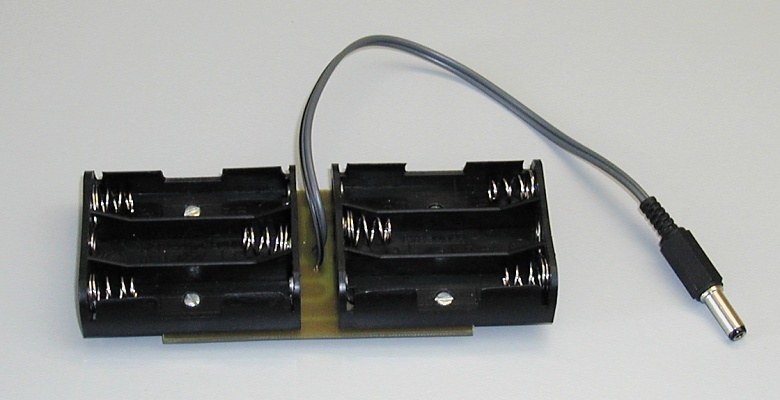
As this circuit was going to be ‘used in the field’ (literally!) I also made a PCB to accommodate two 3 x AA battery boxes, giving me 9V to power the circuit.

The battery boxes mounted on a PCB
The PCB design includes a regulator and diode to protect against over-voltage and reverse voltage, and also to provide a steady 5V to the 1416 and 4029 ICs. Power consumption during use is low since the 1416 has an auto-powerdown function.
Parts list
| Part |
Quantity |
| 10Ω 0.25W carbon film resistor |
1 |
| 1kΩ 0.25W carbon film resistor |
2 |
| 5.1kΩ 0.25W carbon film resistor |
1 |
| 10kΩ 0.25W carbon film resistor |
2 |
| 100kΩ 0.25W carbon film resistor |
4 |
| 470kΩ 0.25W carbon film resistor |
1 |
| 1nF 25V ceramic disc capacitor |
1 |
| 0.1µF 25V ceramic disc capacitor |
6 |
| 4.7µF 16V tantalum bead capacitor |
1 |
| 220µF 16V radial electrolytic capacitor |
1 |
| 1N4001 1A rectifier diode |
1 |
| 1N4148 150mA signal diode |
1 |
| 4069 hex inverter |
1 |
| 1416 voice recorder |
1 |
| 7805 5V 1A voltage regulator |
1 |
| 5mm red LED |
1 |
| 14-pin DIL IC socket |
1 |
| 28-pin DIL IC socket |
1 |
| 3.5mm mono jack chassis-mounting socket |
4 |
| 3.5mm mono jack plug |
4 |
| 5.5mm power jack chassis-mounting socket |
1 |
| 5.5mm power jack plug |
1 |
| Miniature tactile button |
1 |
| SPST toggle switch |
1 |
| 6.6cm 8Ω 0.5W speaker |
1 |
| 10cm x 7cm single-sided PCB (Main PCB) |
1 |
| 1.2cm x 1.5cm single-sided PCB (REC SW PCB) |
1 |
| 8.3cm x 5cm single-sided PCB (Battery Box PCB) |
1 |
| 14.3cm x 8.2cm x 3cm plastic box |
1 |
| Triple AA battery box |
2 |
| 5mm push-fit plastic LED holder with bezel |
1 |
| 6mm M2.5 bolt |
5 |
| 20mm M2.5 bolt |
1 |
| M2.5 nut |
11 |